Tuning in the noise? New electromagnetic circuit simulator visualizes radiation phenomena
Researchers develop highly accurate numerical method for electromagnetic noise that considers both conduction phenomena within conductors and radiation phenomena outside conductors that form electric circuits
Most of the devices used in our daily lives are operated and controlled by electricity. From the standpoint of safety and the tight supply and demand of electricity, circuit design that satisfies low electromagnetic noise and power saving is becoming increasingly important.
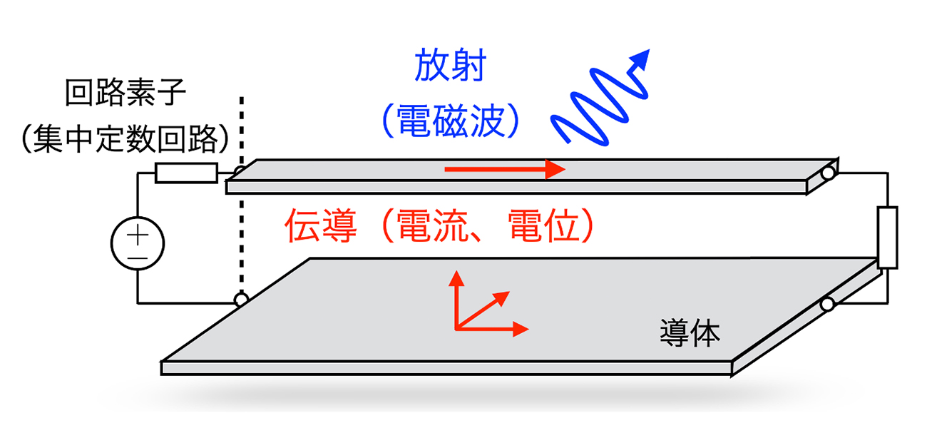
In an electric circuit, electric signals transmit inside the conductor, and electromagnetic fields radiate outside the conductor. Furthermore, the electromagnetic field propagates through the air and is converted into signals for itself and other circuits, which leads to electromagnetic noise. Now, a research team at Osaka University has formulated a numerical method to visualize how signals propagate and radiate depending on the conductor's shape, allowing us to anticipate the causes of electromagnetic noise in the circuit designing stage.
“It is necessary to simultaneously calculate electrical signals and external radiation phenomena to treat electromagnetic noise. To this end, we aimed to precisely solve the delay integral equations of the scalar potential (potential) U and the vector potential A derived from Maxwell's equations, as shown in Fig. 1,” says lead author Souma Jinno.
In the conventional method, as shown in Fig. 2, the delay time is approximated by a constant that does not depend on space, but this numerical calculation is not stable. This research has achieved numerical stability through a numerical calculation (discretization) method that more strictly considers the delay time. The team also developed an algorithm that simultaneously calculates Ohm's law and the equation of continuity and the circuit element of the boundary (lumped parameter circuit).
”We will show the effect of radiation on the conducted signal by applying our method to the circuit shown in Fig. 3 and comparing it with a calculation result that ignores radiation, shown as a red and blue line, respectively. By comparing the two results, we can see that the calculation with radiation is immediately damped and converges to zero, while the calculation without radiation continues to oscillate without damping. Since the conductor's resistance component is assumed to be zero, there is no loss due to conduction. From the above results, the conduction signal current attenuates due to external radiation. The attenuation indicates that a single conductor is not suitable for conducting a signal because of the extensive external radiation. Usually, electrical circuits use two conductors, which can conduct with less radiation,” explains Souma Jinno.
“In order to achieve the Sustainable Development Goals (SDGs), society is moving toward electrification. However, rapid electrification has potential problems such as tight supply and demand for electricity and invisible environmental pollution caused by electromagnetic noise. Using the electromagnetic circuit simulator developed in this research, we aim to realize a ‘sustainable electrified society’ by further reducing noise and power consumption of electric circuits by correctly handling and consuming electric power,” says corresponding author Masayuki Abe.

Fig. 1 Equations used in the paper
As delay time needs to be taken into account to consider external radiation, U and A are affected by the charge density q and current density j, which have some delay times that depend on space. Thus, to precisely consider the delay, it is necessary to perform a complex spatial integration calculation with a time shift.

Fig. 2 Comparison of the treatment of delay time between the conventional method and our method

Fig. 3 Effect of radiation on conducted signals
The red line shows the calculation result with external radiation obtained by the newly developed method, while the blue line shows the calculation result ignoring the radiation by approximating the delay time as zero. The waveform in the graph shows the time variation of the current flowing in the center of the conductor, and its oscillation shows the input pulse current propagating through the conductor, bouncing back and forth at both ends.
The article, “Time-domain formulation of a multi-layer plane circuit coupled with lumped-parameter circuits using Maxwell equations,” was published in Scientific Reports at DOI: https://doi.org/10.1038/s41598-021-83916-4.
Related Links
Professor Masayuki Abe's Laboratory (link in Japanese)
