Elucidation of cause of electromagnetic noise allows for EM noise-less electric circuits
Researchers from Osaka University developed equations for quantifying electromagnetic interference (EM noise) and elucidated its origin, allowing for the best circuit configuration to reduce EM noise
Most common devices are driven and controlled by electric power. Signals and power can be sent by transferring electricity through an electric circuit made up of conductors that conduct electrical current. However, interactions between a circuit and its environment, such as the ground and the earth, generate EM noise, causing malfunctions and generating heat. The equations developed in this study theoretically verified that EM noise was caused not only by the interference between transmission lines, but also by conditions of elements connected to the electric circuit.
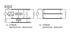
Since it is difficult to find causes of invisible EM noise, various measures based on experience and know-how of trained engineers have been taken to reduce it. To describe EM noise, the researchers used a three-line (multi-conductor transmission line (MTL)) circuit, to which lumped-parameter circuits were connected. In addition to a conventional two-line circuit configuration, another conductor line was connected on the source side as the ground. (Fig. 1)
Thus, this team of researchers derived telegraphic equations, wave equations, and reflection coefficients in the normal mode (NM) that represents circuit signals and the common mode (CM) that is generated by interaction with the environment and causes various noise. Considering the noise mode conversion in the MTL, they derived equations that describe behaviors of the NM and CM.
As a result, they theoretically demonstrated that the CM converted to the NM due to (a) the geometrical relation between the circuit and the environment and (b) the electrical connections between the MTL and the elements connected to the MTL, generating EM noise.
Their method has enabled theoretical calculations of electric circuits with various configurations and electrical connections, confirming that a symmetrical configuration of three transmission lines together with lumped circuits was the only solution to eliminate EM noise. (Fig. 2)
This method enables quantification of behavior of EM noise and time-domain analysis, allowing one to intuitively understand EM noise. This method has the potential to fundamentally eliminate the root cause of EM noise.
Prof. Abe says, “In addition to the improvement of device performances, we aim to develop an ‘EM noise-less infrastructure’ to create a society in which people can use high value-added devices, devices with ultra-low power consumption and ultra-low waste heat.”

Figure 1. Three-line circuit configurations used in this study, which consider the environment around the electrical circuit
(a) Geometrically asymmetric structure / electrically asymmetric connection
(b) Geometrically symmetric structure / electrically symmetrical connection
(credit: Osaka University)

Figure 2. The noise mode conversion from the CM to the NM, which is derived using equations developed in this study
In the electrically symmetric circuit structure (Fig. 1 (a)) and the asymmetric circuit structure (Fig. 1 (b)), the distance d 13 between the circuit, line 1-1', and the surrounding environment, line 3−3′, is changed.
The more the noise mode conversion from CM to NM occurs, the more EM noise is generated. When the noise mode conversion is zero, no EM noise is generated. The EM noise conversion becomes zero only in the electrically and geometrically symmetric circuit structure.
(credit: Osaka University)
The article “Mechanism of common-mode noise generation in multi-conductor transmission lines” was published in Scientific Reports at DOI: https://doi.org/10.1038/s41598-019-51259-w .
Related links
